The film Good Will Hunting popularized problems in graph theory related to generating homeomorphically irreducible trees as solved by the brilliant titular character. Such trees have no vertices of degree 2, meaning that none of the nodes have exactly 2 edges coming out of them. I have most commonly seen mathematical sources outside of references to the movie refer to these graph structures as series-reduced trees, which I believe to be a better descriptor, especially for the purpose of relating graph theory to electrical circuit design.
When I was sitting in physics class (it seems like that's when all of my epiphanies have been happening these days), I noticed some interesting properties of circuits that are suited for correlation with graph theory. For example, the fact that Ohm's and Kirchoff's Laws apply to each sub-circuit of the overall circuit recalls a similar property displayed by trees and subtrees, as during pre/in/post-order traversals and other naturally recursive tree operations. My line of thinking of circuit diagrams in terms of graph theory led me to the observation that in a series-reduced tree, the idea of a series correlates to a circuit wired in series.
To reiterate, a series-reduced tree has no node with exactly two edges coming out of it. Because it is series-reduced, the configuration can be thought of as disallowing a series, or visually a line, of two edges to go directly through a node. Series in this sense means about the same thing as with circuits; a diagram of a circuit wired in series shows a direct passage of the wire through components. In other words, there are no junctions in the circuit, which correspond to branching in a graph representation. With that in mind, a simple series circuit diagram
can be linearized and then represented as a graph.
Note that the positive and negative terminals of the battery are considered as two components, with node values representing their voltage. The resistor becomes a node with its resistance as the value, and the values for current become edge weights. The above is the simplest form of a circuit with all three values. I say simplest, and there would justifiably be objection to such a statement because the 6Ω clearly has two edges. However, I do not collapse it because the nodes to which it is connected are not of the same quantity; so basically, I consider the resistor aspect of the graph series-reduced. Note that in the wire (edges), the currents are equal on either side of the resistor because there is no junction in the series circuit. A simple parallel circuit diagram can be converted to a graph in a manner similar to that shown above
and then expressed in reduced form as a series circuit with one node representing the equivalent resistance of the parallel circuit.
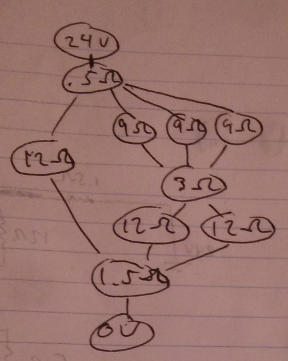
Note that on either side of each parallel resistor node, the currents are equal because they are each in series with the battery terminal and in parallel with each other. When we combined the parallel resistance, we also summed the currents according to Kirchoff's Junction Rule. Now that I've explained that, I will now proceed to do something contrary to myself and omit the currents from my drawings, because the calculations are only focused on finding equivalent resistances right now. The way I reduced the two parallel nodes seems a little arbitrary when it's only hooked up to the voltage nodes, but take the following combined diagram as a significantly less simple example.
If we were to draw this as a graph, we would come up with the following (oriented for descending electric potential).
First, apply series reduction, or the collapsing of all 2nd degree vertices, to each pair of resistor nodes that are in series with each other. The concept of a series reduction operation follows from the aforementioned definition of series-reduced tree. We now have the following as our graph.
Observe that there are now no two resistor nodes that are both in strictly in series. However, there are nodes that are in series to more than one other node (which are in turn parallel to each other). I can't series reduce the 12Ω with the .5Ω and the 1.5Ω because they both have other nodes attached. Hopefully now it makes more sense that I collapse these parallels into one equivalent series. I collapse the most complexly nested parallel setups first, which makes sense when you consider that I cannot collapse the outermost parallel between the .5Ω and the 1.5Ω because the right side still has parallels within it. Parallels can only be collapsed when the individual parallel components are in series. With that in mind, I reduce the circuit to the configuration below.
It should seem pretty clear what to do next; series reduce the right branch of the junction. Notice we are alternating between parallel reduction and series reduction.
The multiple branches in parallel between the .5Ω and the 1.5Ω are now represented each as a simple series. The parallel can now be reduced.
Finally, we series reduce one last time to arrive at the simplest form.
Nice.
Did a graph theoretical representation of a circuit diagram teach us anything we didn't already know? Admittedly, not really; the algorithmic approach used above is the same as how I would approach finding the equivalent resistance of a diagram. Does the analogy fall apart in certain places? It's possible, naturally. However, it appears as an interesting cross-subject correlation that provides a different way of approaching a common problem. Toying with the conventional representation of circuits may lead to easier implementations of circuit calculators, or something else cool that I haven't considered. It could even just serve the purpose of a fun, creative thought exercise. Perhaps someday soon I will have another epiphany and explore the idea further, but for now, enjoy the pretty pictures!